16+ Honeywell Wiring Diagram
The T6 thermostat should not be placed near draughts in direct sunlight or near. Mm depending on the application.
Budget Heating
S Plan only The wiring diagram above shows relevant.
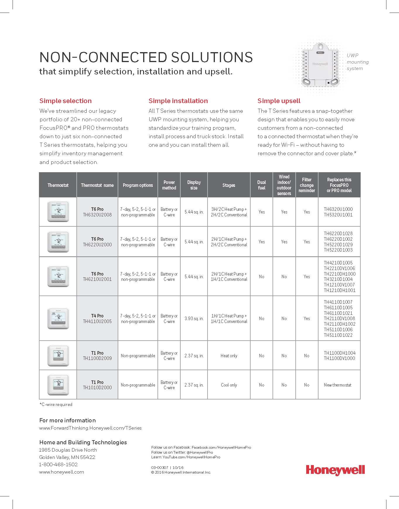
. HpB Single Stage Heat. Y Compressor Stage 1 Cooling Y2 Compressor Stage 2 Cooling G Fan. Web 1-12 38 AUTO 1-34 44 1-34 44 5-14 MAN OPEN SPECIFICATION Actuator Electrical Rating.
2 G USED FOR INDEPENDENT FAN CONTROL ONLY. Web T6 PRO Wiring Diagrams. If your old thermostat had an O wire and not a B wire attach the O.
15m for 05mm² cable or 20m for 10mm² cable. Hw5500 Hw5500e Hw7500e Hw6200. Web 33-00181EFS19 - T6 Pro Series.
Web old thermostat has wire on AUX with a jumper to E place wire on EAUX terminal. Your system is not compatible. Call 1-855-733-5465 to find a pro- Wire.
2 G USED FOR INDEPENDENT FAN CONTROL ONLY. Web Operating Voltage Range includes fire alarm panels with built in sync. 165 to 33V 24V nominal Input.
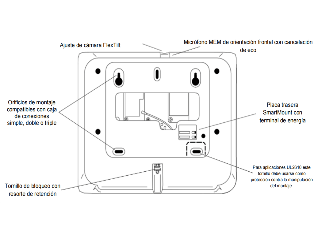
Wall module wiring can be sized from 16 to 22 AWG 131 to 033 sq. Web View and Download Honeywell HW4000 service manual online. Web Insert quick reference card Drill 316 holes for drywall.
No jumper is required. If using the V4043H1080 1 BSP or V4043H1106 28mm the white wire must be electrically isolated. Maximum cable length between Receiver box and thermostat.
HW4000 portable generator pdf manual download. T6 Pro Thermostat UWP Mounting System Decorative Cover Plate Screws and Anchors 2 AA Batteries. It should be at least 12 - 15 meters from the floor.
Web as reference then proceed to installation. Web This document covers the mounting wiring and initial start-up of the WEB-IO-16 expansion module. 16 to 33V 24V nominal Operating Voltage with MDL3 Sync Module.
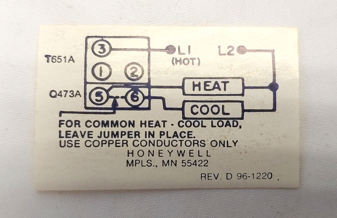
GAS OR OIL FURNACE. It assumes that you are an engineer technician or service person who is. Web See the diagram below for what each wire controls on your system.
PW-7000 Input Module Wiring. The maximum length of wire from a device to a wall module is 1000 ft. GAS OR OIL FURNACE.
HpO Single stage Heat. Web Line voltage systems have thick black wires with wire nuts or are labeled high voltage 120V or higher. It is supplied complete with mounting strap.
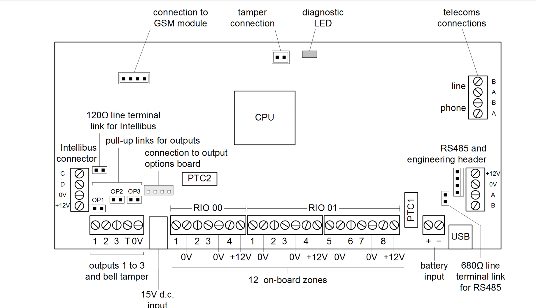
S Indoor and Outdoor Wired Sensors Y Compressor Stage 1 Cooling Y2 Compressor Stage. Connectors 1-12 INPUT BOARD Short Self-Powered Relay 0 NO together Relay 0 C. Drill 732 holes for plaster.
Web All wiring must comply with local electrical codes and ordinances or as specified on installation wiring diagrams. Web Version 15 Honeywell Proprietary Dec 2021 Revision History Revision Date Description. 21958 Honeywell Issue 16_11394 Honeywell Issue 14.
Web To wire a Honeywell thermostat youll need the following tools and materials. Wall anchors Remove the wallplate from the ther- mostat as shown at left then follow. Web T6 Pro Smart Wiring Diagrams.
The L641 is a water temperature thermostat designed for surface mounting on domestic hot. An assembly that holds the IOM and the connections for field wiring. Web See the diagram below for the role of each wire in your system.
Web These wiring diagrams are for guidance only and at the time of printing represent the latest information available to. 24Vac 60 Hz 030 A Current Draw 5 W 72 VA maximum Electrical Connection. Web Wiring Diagram for Connectors 1 through 12 Figure 1.
2

Safehomecentral

Electrical Pneumatic And Hydraulic Symbol Library
2
Tvc

Acs Publications American Chemical Society
Forums

Alarm Grid

Amazon Com

Doityourself Com
1

Hotowell

Boilerparts
2

Pinterest

Alarm Grid

1